In this fourth part, I’m going to finally mount a circuit using the ATmega8 microcontroller and program it with the firmware we wrote.
Go to: part 1, part 2, part 2.1 (video), part 3, part 4 (video), source-code.
Whoa! It has been a long time since my last part… about 3 months! Anyway, let’s finally put the firmware we wrote on part 3 into the microcontroller.
The circuit
ATmega8’s I/O ports
If you’ve read the C or assembly code from part 3, you must remember that it just writes some values to ATmega8’s PORTC.
ATmega8 has three multi-bit multipurpose I/O ports: PORTB with 8 bits, PORTC with 7 bits, and PORTD with 8 bits. Each of these bits are mapped to one pin at microcontroller, but most pins have multiple functions. For example, 4 pins from PORTB are also used for the Serial Peripheral Interface (3 of them are used to program the microcontroller using serial programming); 6 bits from PORTC are also used for Analog-to-Digital Converter (while 2 of them can also be used for the Two-wire Serial Interface).
While we can choose to use any one of the available functions of each pin, there is one special pin that I think should not be messed with: the RESET pin. While we can use it as PC6 (bit 6 of PORTC), doing so will require disabling the reset line, which means that we won’t be able to use serial programming anymore, which means that ISP (In-System Programming) won’t be possible, which means that our simple and cheap AVR ISP programmer we built on part 2 won’t work, which means that parallel programming must be used instead, which requires much more wires and components, which adds a lot of complexity… Well, all of this just because we wanted to have 1 more I/O bit. Is it worthy? I don’t think so.
Of course, you can read all the gory details about ATmega8 at its datasheet.
Our circuit
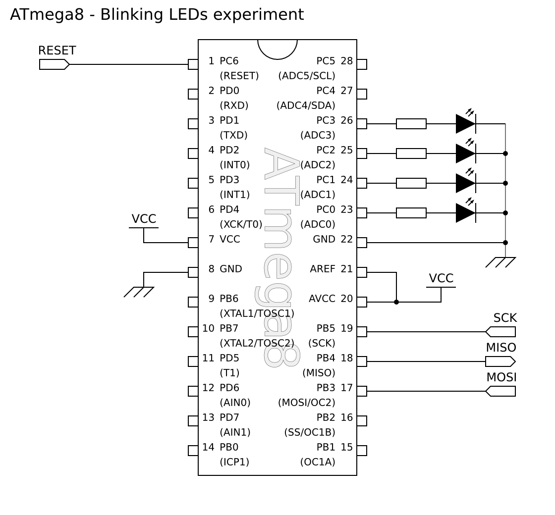
I’ve decided to use the 4 least significant bits from PORTC to connect the LEDs, but any set of free pins could have been used instead (of course, with appropriate changes to the firmware source code).
The circuit itself is dead simple. I’ve just connected one LED and one resistor to each output pin used. In addition to that, I’ve connected my ISP connector to the RESET, SCK, MISO and MOSI ports. Finally, just connect all GND together and connect the VCC to the microcontroller. There are two things that should be noted, though:
First one is that our parallel port ISP programmer is unpowered (i.e. it doesn’t draw current from the PC’s parallel port, but only transmit signals). This means we need to get 5V VCC from somewhere else. In my case, I’ve used an USB port to do so.
The second thing is that I’m using 4 resistors, one for each LED. It is also possible to use only one resistor for all LEDs, but this means that when multiple LEDs are on, they will appear dimmer than when separately lit.
Here is the circuit (drawn using Inkscape):

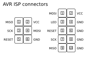
The RESET, SCK, MISO and MOSI lines come from the ISP connector. Although my programmer does not use a standard connector, the pin numbers are the same as the standard one. To help you remember such connector, here is the pinout:
Update on 2008-12-02: Originally, the 6-pin pinout was wrong. It has been fixed, so the pinout below is correct.
Step-by-step mounting (with pictures!)
Well, I think I didn’t really need to guide you step-by-step on how to mount this circuit on the breadboard (AKA protoboard), but I have some pictures I wanted to show. :) (this time, the photos were taken on a Sony DSC-S80 digital camera, with additional light by SonyEricsson K750i flashlight, and then I applied Layer → Colors → Auto → White Balance on Gimp)
The first step is to insert the 28-pin socket on the breadboard and then insert ATmega8 on the socket. Also insert the ISP connector.
In the next picture, I’ve also connected the GND and VCC lines. As you can see from the above circuit diagram, three microcontroller pins are connected to VCC and two are connected to GND.
Note that this breadboard is unpowered! Be careful if your breadboard is powered by any external source!
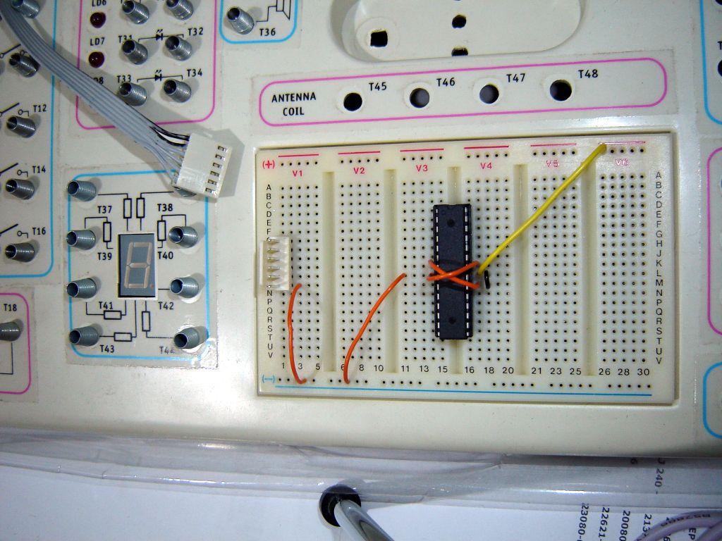
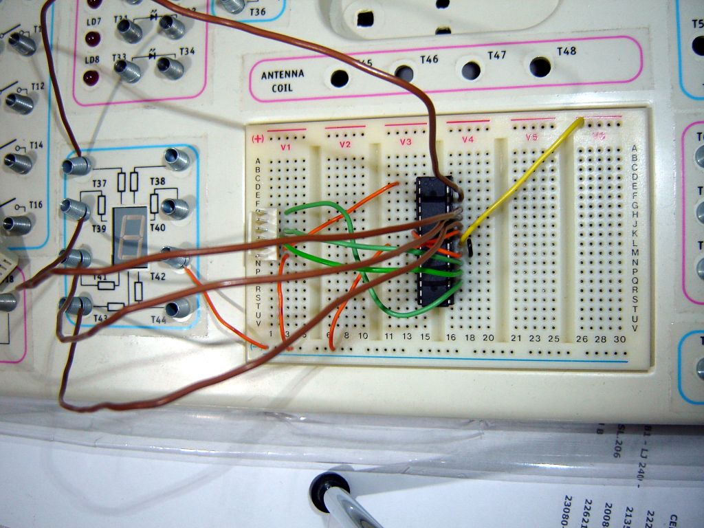
Then, I connected the ISP pins to the microcontroller. Since my ISP programmer is unpowered, I left VCC line from it not connected.
The wire colors here don’t mean anything special. I just happened to have pieces of wire with different colors for different lengths. Makes it easier when working with the breadboard.
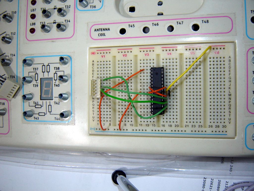
Next, I added wire connections to the LEDs. I fortunately have a 7-segment display already mounted near the breadboard with one 2K2 resistor for each segment. In case you aren’t as lucky as I am, you need to insert the resistors and LEDs on the breadboard. I guess any resistor between 1K and 2K should be enough. Also be careful to not invert the LEDs, or they won’t turn on.
Finally, I connected my ISP programmer to the connector on the breadboard. I also added USB power to the board, by connecting USB +5V and USB GND wires to VCC and GND lines of my circuit.
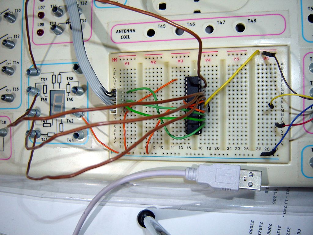
If you remember the part 1 you will notice I listed a USB-B connector at the parts list. However, later I noticed this connector can’t be used on a breadboard. Since I still want to get power from USB (and, later on, make ATmega8 act as an USB device, but not in this post series), I bought the cheapest USB cable I could find (R$ 2.79, or US$ 1.57), ripped one of the ends and used the wires on the breadboard.
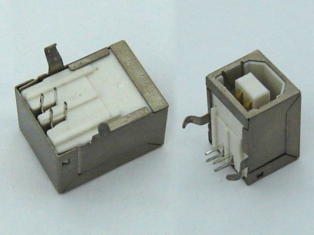
This USB-B connector will be saved for future projects. (Update on 2011-08-10: It turns out I’ve never used that USB-B connector, and I don’t think I will ever use it.)
Preparing the operating system
As described in part 1, you need to download/compile avrdude. Probably uisp or PonyProg should work too, but I’ve choosen to use avrdude because I feel it is the most complete and versatile program. In addition, its documentation is pretty good.
Supposing you are on Linux, you need to enable ppdev kernel module (Device Drivers → Character devices → Support for user-space parallel port device drivers). After loading this module (by running modprobe ppdev, and optionally adding it to /etc/modules.autoload.d/kernel-2.6/etc/conf.d/modules on Gentoo), make sure the parport device has appropriate permissions (ls -l /dev/parport*). On my system, I can just add my user to the lp user group.
If you are on Windows, you may try using giveio (Wayback Machine). I think it is also distributed with avrdude. I don’t use Windows, I can’t provide any help on that.
That’s all you need, but, before continuing, I recommend reading the avrdude documentation or its manpage.
Learning more about your microcontroller
The AVR microcontrollers have three types of memory:
- A relatively large non-volatile Flash memory (8KiB, in ATmega8), where the program code and data (firmware) is stored. Big chunks of constant data should also be stored here. It can only be written or erased in blocks (called pages). The program running on the microcontroller can read single bytes from it.
- A relatively small, but fast and volatile SRAM (1KiB, in ATmega8). Since this is volatile, it is not possible to access it or write to it using avrdude (and it doesn’t make sense, anyway).
- A relatively small and non-volatile EEPROM (512 bytes, in ATmega8). Single bytes can be read or written, making it perfect for storing small portions of data that must be preserved even when power is off.
In addition to them, there are some special programmable bytes (this information might be inaccurate for devices other than ATmega8, please check the datasheet of your device):
- Lock bits, stored into one lock byte, control the ability to read/write the EEPROM and the Flash memory. These bits can only be erased using the chip erase command, which will also erase the other memories.
- Fuse bits, stored into fuse high byte and fuse low byte, control several features of how the microcontroller works. The most important are the bits which control the clock source (in other words, if the microcontroller will use an external crystal, an external clock, or the internal oscillator, and the frequency of the internal oscillator).
It may seem weird, but these bits are called programmed when set to 0, and unprogrammed when set to 1.
avrdude can read and write all of them (except the SRAM, of course). Usually, though, you only need to set the fuse bits once, and (re)program the Flash and EEPROM memories as needed. When the final product is ready, you may set the lock bits if you want.
Using avrdude to program the microcontroller
Common parameters
There are some parameters you want to always pass to avrdude:
-p atmega8 -c bsd -P /dev/parport0
Ok, I know that -P is optional, but it doesn’t hurt to use it.
There are some other parameters you might like (please, read the documentation or the manpage to find out more about them):
-E noresetThis forces avrdude to leave the RESET line deactivated before exiting, allowing the microcontroller to start the program even with the ISP hardware connected. By default, avrdude will leave the parallel port in the same state that it was found.-nDisables writing any data.-vEnable verbose output.-i {delay}This changes the default delay between each bit change. Increase this delay and connect the ISP pins to a couple of LEDs instead of the microcontroller to see how avrdude sends commands to the microcontroller. (Basically, you will see some blinking LEDs.)
More about the fuse bits
When programming the microcontroller, make sure the fuse bits select the desired clock source. The default value on my microcontroller selects the internal oscillator at 1MHz. Since for this project I didn’t care about the clock, that was ok.
However, if the fuse bits select an external clock source, you must add this clock source to your circuit (e.g. add a crystal and two capacitors) before being able to even program the microcontroller (like shown at page 237 from ATmega8 datasheet).
Calculating the fuse bits can be a bit boring, so fortunately someone else has made an AVR Fuse Calculator. You might find it handy. Note, however, that the default fuse bit values for ATmega8 in that page are incorrect. (Update: It has been fixed.) As described at pages 223 and 224 of ATmega8 datasheet, the default values are actually 0xD9 for the fuse high byte and 0xE1 for the fuse low byte.
Programming the microcontroller
Supposing that the external clock source is correctly connected, or that you don’t need one because you are using the internal oscillator, then we can run avrdude and it will be able to talk to the microcontroller.
avrdude -p atmega8 -c bsd -P /dev/parport0  \
  -U signature:r:signature.dump:h
This command will just read the signature bytes from the microcontroller and save them to the signature.dump file, using hexadecimal format. In my case, that file was created with these contents:
0x1e,0x93,0x7
What do I need these bytes for? Actually, for nothing. But this is an easy way to test if avrdude can talk to the microcontroller, without writing anything to it. It also confirms the model of the microcontroller (each model has a different signature).
Use the following command to write the new firmware into the microcontroller:
avrdude -p atmega8 -c bsd -P /dev/parport0  \
  -U flash:w:hello.hex:i
This will program the hello.hex file, stored in Intel Hex format (ihex) (Wayback Machine), to the Flash memory.
avrdude automatically verifies the written data after issuing the write command. The verification is done by reading data from the microcontroller and comparing with the local file. If you want to disable this automatic verification, use -V (but there is no real reason to disable that).
Yet again, please check the documentation or the manpage to understand how to use the -U parameter. It’s really simple and easy. You can also pass multiple -U parameters at the same command line. For instance, the following command will read basically everything from the microcontroller and save on different files using different formats:
avrdude -p atmega8 -c bsd -P /dev/parport0  \
  -U flash:r:flash.dump:i \
  -U eeprom:r:eeprom.dump:i \
  -U hfuse:r:hfuse.dump:b \
  -U lfuse:r:lfuse.dump:b \
  -U lock:r:lock.dump:b \
  -U signature:r:signature.dump:h
Obviously, these command lines are too big to type them manually, and you should add them to the Makefile. See part 3 for some sample Makefiles.
When things don’t work…
Who said all of this would work right away? I didn’t! Of course that it won’t work!
The most common cause of failure is bad contact between the microcontroller and the breadboard. Sometimes not all pins are touching the breadboard contacts. There is no real solution for this, just try pressing or bending the microcontroller or its socket very gently. Be careful not to break the pins.
If you can’t seem to make it work on a breadboard, try soldering the socket onto a stripboard or a PCB.
Don’t you like this idea? Me neither. This is why I think hardware sucks! Hardware is always a source of faults! 😉
Update on 2008-07-04: Anibal points out at the comments (Wayback Machine) that there is an important BIOS setting that plays a role here. If the parallel port is configured as SPP, then the communication is unidirectional (data can only be sent, but never be received) and thus avrdude won’t be able to talk to the microcontroller. If this happens to you, changing that setting to EPP+ECP should fix the problem. Thanks, Anibal!
Be happy and watch the blinking LEDs!

Well, if everything went fine, you should have some blinking LEDs right after running avrdude. Maybe you need to unplug the ISP hardware, maybe not (this is why I use -E noreset).
I’ve uploaded a simple video of this experiment to YouTube. The camera was a Sony DSC-S80, the video has been put together in blender (using its sequencer).
This is the last part of this series. I think I’ve successfully documented everything I learnt from this experiment. I hope these posts will be useful for other people, like they will be useful for me in the future, whenever I forget one detail or another.
I plan to make at least a few more projects using ATmega8, and maybe some others using other microcontrollers. I’m going to post them here if I feel they are worthy enough.
Thanks for reading, see you next time!
Update on 2011-08-10: I’ve added part 2.1 (and a video) that uses a USB programmer, instead of the parallel port programmer that I’ve originally used. I haven’t updated the instructions above on how to use avrdude, but I guess you can figure it out.
Go to: part 1, part 2, part 2.1 (video), part 3, part 4 (video), source-code.