In this second part, I’m going to build an AVR programmer to be connected to the PC’s parallel port. I’m trying to summarize here all information I found spread all over the web. I believe this post is worth reading even if you don’t have a parallel port, as it describes how AVR programming works.
Go to: part 1, part 2, part 2.1 (video), part 3, part 4 (video), source-code.
What is an AVR ISP Programmer?
ATmega8 (as well as many other microcontrollers) has a feature called ISP (In-System Programming), which means they can be programmed while still connected to the final circuit. You do this by sending electric signals to the microcontroller; there is no need for UV light, like many chips from the last century. In other words, it means that it is very easy to program the microcontroller.
By programming the microncontroller I mean writing a new firmware on it. And the firmware is the software you are going to write to be run inside the microcontroller.
Available AVR Programmers
There are many types of AVR Programmers available for sale everywhere. Most of them are somewhat expensive. Some of them use the parallel port, others use the serial port and others use a USB port. Some may require external power supply.
At Cerne-Tec (the place where I bought ATmega8), they sell a programmer for R$ 89.90 (about US$ 50.50), which is nine times the price of the microcontroller itself! I really don’t know what kind of special features it has, but I won’t spend so much money if I can build a working one for R$ 8.80 (maybe even less, if you happen to have some components). For DIY projects, it’s more than enough.
How AVR Programming works
ATmega8 (and probably other AVR microcontrollers too) has two methods of programming: parallel programming and serial programming. The former uses 17 pins (plus 3 for Vcc and GND) to send all data and control commands in parallel. The latter uses just 4 pins (plus 3 for Vcc and GND) and send commands and data in serial. This means that serial programming requires less wires and may use a smaller connector. In addition, serial programming looks simpler than parallel programming (4 pages versus 11 pages at ATmega8 datasheet).
Serial programming uses almost the same pins as the SPI (Serial Peripheral Interface); the SS (Slave Select) pin is not used. It works by sending a RESET signal at the RESET pin, which will… huh… reset the microcontroller and enter the serial programming mode. Then, the commands are sent at the MOSI (Master Output, Slave Input) pin and the clock signal is sent at the SCK (Serial Clock) pin. Data sent from the microcontroller back to the programmer (or to the computer) goes through the MISO (Master Input, Slave Output) pin. And that’s all you need to know! (refer to Serial Programming section at ATmega8 datasheet, pages 230-233)
The AVR ISP Parallel Port Programmer
You must be asking to yourself: Why did this guy describe the serial programming method if we are going to use the parallel port? The answer is simple: we are going to use the PC parallel port to transfer serial data to the microcontroller serial pins. This works very well because the complicated (well, not so complicated) logic of sending the required bits at the exact time and the exact order is done by software. The parallel port will just receive some bytes (which are just a couple of bits together) and set the respective pins high or low, which will be directly (except by resistors) connected to the microcontroller pins. This means the parallel port programmer dongle is the cheapest programming hardware you can build: it has just the connectors, the wires and some resistors.
While searching the web for instructions about how to build it, I found many sites with different ways of connecting the parallel port pins. This made me confused about which one I should try to build, and which one would work. After looking at /etc/avrdude.conf file, I understood that all of them (or at least most of them) will work, even though they are different. You just need to select the correct programmer type in your programmer software (be it avrdude, uisp (Wayback Machine) or even PonyProg (Wayback Machine)).
I found basically 3 different schematics almost everywhere. Unfortunately, not all of them looked similar at first sight, and also not all of them had a name describing what type of parallel port programmer it was. Fortunately for you, I’m going to list here these three schematics with their respective names.
The schematic diagrams below were drawn by me using Inkscape. I release these images as public domain, but I would love to be credited if you use them. Note: these circuits are not my creation.
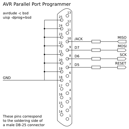
bsd
The first one is called bsd, probably because it was originally available at AVRPROG program for FreeBSD. (Well, I’m not sure if this is true, but it’s the best explanation I have to give you.) This program was later renamed to AVRDUDE to avoid confusion with Atmel’s AVRPROG.EXE. You can find a description of this parallel port programmer at AVRDUDE old homepage (Wayback Machine).
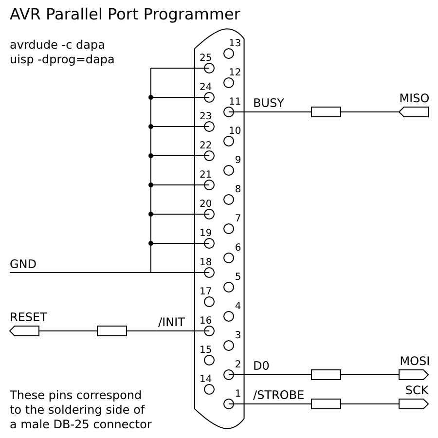
dapa
The second one is called dapa, which means Direct AVR Parallel Access cable. This one is described at uisp-parport-connect.txt file from uisp (Wayback Machine). It is also found at Arduino’s ParallelProgrammer page (Wayback Machine) and at LinuxFocus 352 article (Wayback Machine).

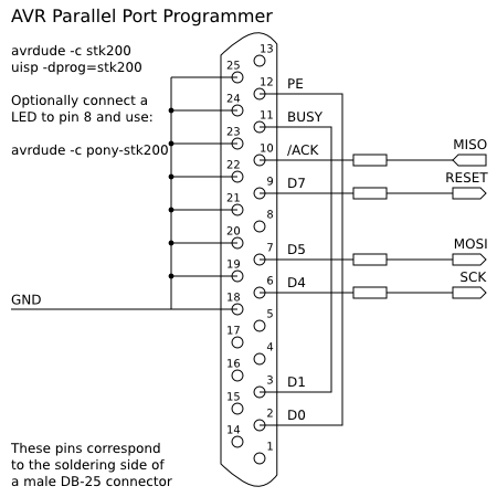
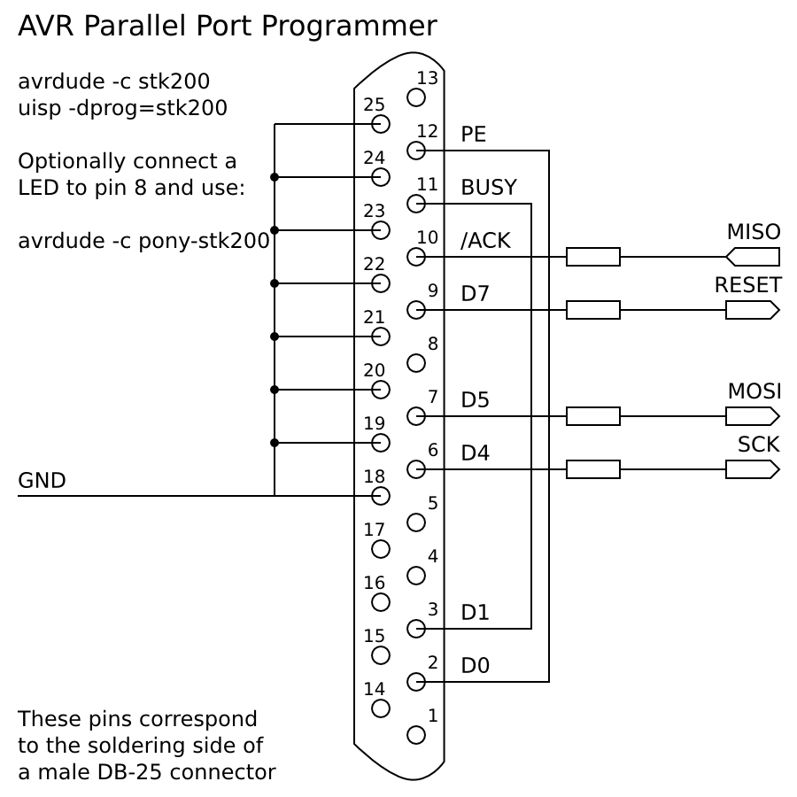
stk200
The third one is called stk200, because it behaves like the STK200 AVR Starter Kit. It is the schematic used by How To…Build A DIY USB Joystick (Wayback Machine) project and is also available at a personal homepage address found at #avr channel topic (Wayback Machine) on FreeNode.
Other similar designs
While writing this post I also found another design (Wayback Machine). It’s the one used by SpokePOV (Wayback Machine) project. There is a kit available for sale (Wayback Machine). It works like the DT006 AVR Development Board (the little rAVeR programmer) (Wayback Machine) and is recognized by avrdude and uisp as dt006. Sorry, I don’t have the schematic diagram for this one, but don’t you think that 3 different schematics are more than enough?
Notes about the parallel port dongles
The first thing to be noted is the absence of a Vcc line. This happens because the parallel port can’t supply enough power. This implies that the microcontroller must be powered by something else (like the USB port or batteries) while using these dongles.
You can also see I’ve connected 8 pins to the GND wire. I did that because the parallel port has 8 GND pins, but you are not required to solder all of them together. You can use just one GND pin and it shoud be enough.
Another thing to be noted are the resistors. I’ve not specified their values because each site used different values (and sometimes the same site used different values). The stk200 schematic from How To…Build A DIY USB Joystick (Wayback Machine) (direct link to the image (Wayback Machine)) uses 4 resistors of 330 Ω each, one for each line (of course, GND is not included). On the other hand, this personal homepage (Wayback Machine) tells us to use 4 × 220 Ω, but also hosts an image that shows one 100 Ω resistor for the MISO line and 3 × 330 Ω for the other lines.
Both Arduino’s ParallelProgrammer page (Wayback Machine) and LinuxFocus 352 article (Wayback Machine) use the dapa schematic and both use the same values for resistors: 220 Ω for the MISO line, 470 Ω for the SCK and the MOSI lines, no resistor for the RESET line. In addition, the LinuxFocus 352 article (Wayback Machine) says the cable should not be longer than 70 cm.
The old AVRDUDE homepage (Wayback Machine) does not even give many details about this: “Be sure and include series resistors between the signal wires and the parallel port. 1K resistors should work fine and may save your parallel port from damage in case of mis-wiring or some other mishap.”
Finally, the dongle used in SpokePOV project (Wayback Machine), which works as dt006, uses 3 × 1K Ω and one 47 Ω.
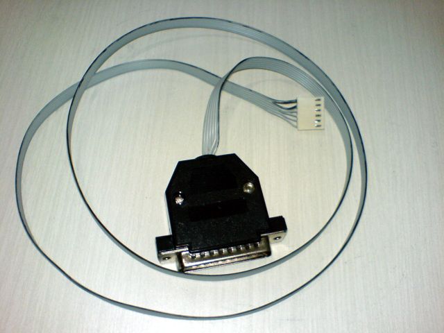
My conclusion about this: put some resistors and avoid too long cables. I’ve used a 220 Ω resistor for the MISO line and 3 × 330 Ω resistors for the other lines. My cable is 1 meter long.
If you run into problems, read this post at AVR Freaks forum (Wayback Machine) and try shortening the cable length, or try using one of the other (a little more expensive) programmers listed below.
My parallel port AVR programmer
From all possible dongles above (and below), you just have to choose one to build. All of above are very similar to each other, and all of them should work on both avrdude and uisp (Wayback Machine) (and both programs are available on multiple platforms).
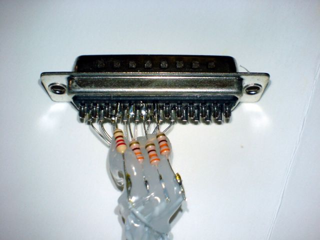
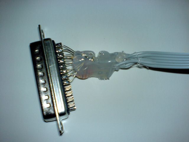
I’ve choosen to build the bsd one. I got a flat cable with 14 wires, but since I needed only 6 (actually, only 5), I’ve split the cable. To make sure the wires wouldn’t short-circuit inside the DB-25 case and to make everything inside the case less likely to break, I’ve applied an amount of hot glue after I finished with the soldering. If you look at the photos, the dongle looks a bit messy and ugly, but since that hot-glued part will be hidden inside the DB-25 case, no problem!
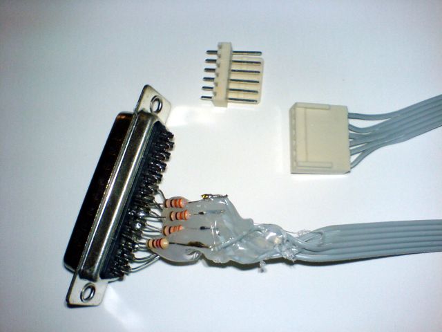
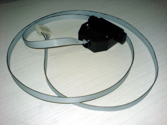
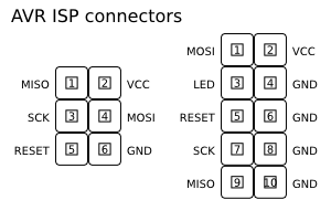
I’ve not used any standard AVR connector for this project, but I will, if I build another programmer. Things will be easier in future if you use the standard 6-pin plug (or the 10-pin, but I prefer the 6-pin one), just in case you happen to use another programmer with your project, or your programmer with another project.
Update on 2008-12-02: Originally, the 6-pin pinout in this blog was wrong. It has been fixed, so the pinout below is correct.
Even though I have not used the standard connector, I kept the same wire order as the 6-pin one. Then, I tried to use the following pen to mark the wire 1 as black:
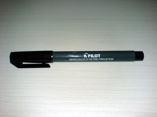
Unfortunately, it was not a good choice, because the painted portion of that cable now leaves a black stain everywhere it touches.
The photos above were taken using a SonyEricsson K750i phone at full resolution (2 megapixels). Then, I used Gimp to scale down the images after applying Layer → Colors → Auto → White Balance.
Other DIY AVR Programmers
Update on 2011-08-10: This section is now somewhat obsolete, as I’ve just written part 2.1, which deals with USBasp programmer. If you prefer, skip the rest of this post and go directly to part 2.1.
Buffered parallel port
That personal homepage address found at #avr channel topic (Wayback Machine) has a link to a PDF schematic diagram (local mirror) (Update on 2008-12-02: be careful, the pinout in this PDF is wrong) that describes how to build a buffered parallel port dongle. It uses one 100K pull-up resistor, one 0.1µF decoupling capacitor, and a 74HC244 buffer chip. A similar diagram can be found elsewhere on the web (Wayback Machine).
I’m not sure, but as I understood the schematics, this dongle will get the needed Vcc from the microcontroller connector.
Serial port
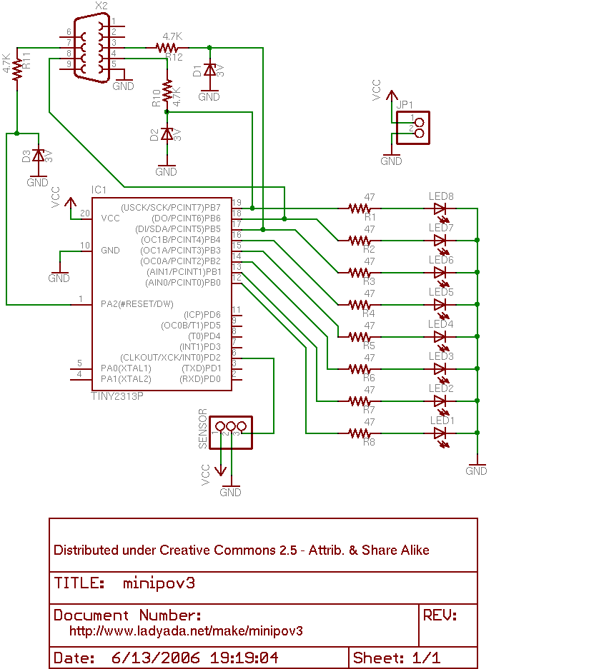
The MiniPOV3 (Wayback Machine) DIY project uses a serial port to program the chip. This works in a similar way to the parallel port programming, but requires some diodes too. You can see the schematic diagram (Wayback Machine) at Design link (Wayback Machine). You can also see a page dedicated to the serial dongle (Wayback Machine) at SpokePOV (Wayback Machine) project.
Personally, I don’t see enough good reasons to use the serial port over the parallel port. The only good reason is the size (a serial port is about half of the size of a parallel port). However, I guess that, if a PC does not have a parallel port, most likely it won’t have a serial port either. In addition, the serial port programmer requires a few more componentes (3 diodes). Finally, it uses a method called “bitbanging”. I don’t like this name, it sounds too hackish and cheap for me.
USB port
There is a so-called inexpensive USB AVR programmer (Wayback Machine). You can buy the kit (Wayback Machine) with all needed components for US$ 22.00, or you can use the instructions and find or buy the components by your own.
This programmer is more complex. It uses an AVR microcontroller and some tri-state buffers. It will be difficult (or impossible, or at least ugly and messy) to build this without a PCB or a stripboard. It also has two LEDs (one red and one green) to display the current status. If you buy the kit, this programmer looks pretty neat because of the case and the LEDs.
This programmer is also good because it can use the USB to give enough power to the microcontroller being programmed, avoiding the need of external power supply, unlike the parallel/serial programmers.
In my opinion, if your PC has neither the parallel port nor the serial port, but has at least one available USB port, and you don’t want to buy a USB-to-Serial or a USB-to-Parallel adapter, then this is the programmer you should build (I’ve changed my mind, see the update below).
On the other hand, there are some disadvantages with this project. The first one is the price (US$ 22.00 versus US$ 7.50 for the parallel/serial dongle kit at the same site (Wayback Machine)). The second one is the need for a USB A-B cable. Of course you must have at least one of this cable lying around somewhere (or at least one connecting your printer or scanner), but the parallel/serial programmers don’t need any extra cable. Ok, I know this is easy to fix. Just get a cable, cut one of the connectors and solder the cable to the dongle.
Another disadvantage is the buggy libusb on 64-bit architectures, as you can read on FAQ (Wayback Machine). It also looks like you need to be root to use libusb and this device (but I’m not sure), while it’s not needed with parallel/serial programmers (I need to get root once to change permissions of the /dev/something device or to add my ordinary user to some group).
Yet another disadvantage is the difficulty to build this dongle without buying the kit. You must buy two chips and a PCB or a stripboard and solder everything together. The buffer chip should be easy to find (but I don’t know if it really is). The ATTINY2313-20PU chip, however, might not be so easy. I found ATmega8 and ATmega16 at Cerne-Tec (which is located in Rio de Janeiro, where I live), but only these two models are sold there, they don’t sell ATtiny. Probably I can replace the ATtiny with ATmega, but it will probably make the project a bit more expensive. Finally, whenever you get the microcontroller, you still need to program it with the USBtinyISP firmware, but how? (the “chicken & egg” problem) Well, you can use someone else’s programmer, or you can just use a serial or parallel programmer. But, in the latter case, why don’t you just use that programmer for everything else?
Update on 2008-01-03: I’ve just found another USB ISP programmer. It’s called USBasp (Wayback Machine). “It simply consists of an ATMega48 or an ATMega8 and a couple of passive components. The programmer uses a firmware-only USB driver, no special USB controller is needed.” After reading this, I’ve changed my mind. If I ever need to use an AVR programmer on a PC without parallel port, I will build this one.
I’ve read at a page with instructions about USBasp (Wayback Machine) that you should connect the programmer to a port on the computer, avoiding USB hubs. I’m not sure if this is the case of other USB programmers, but since nowadays computers fortunately have many USB ports, I hope this won’t be a problem.
Update on 2011-08-10: I’ve bought a USBasp, and I’ve also built one on a breadboard. Everything is described in detail at part 2.1.
Other links
- PC parallel LPT port pinout (SPP) (Wayback Machine)
- ECP Parallel LPT port (IEEE-1284A) pinout (Wayback Machine)
- Information about using AVR ISP programmers
Go to: part 1, part 2, part 2.1 (video), part 3, part 4 (video), source-code.