A few weeks ago, I did what I wanted to do for a long time: I built my own RetroAdapter (Wayback Machine).
RetroAdapter (Wayback Machine) is an open-source project that uses an 8-bit AVR microcontroller (ATmega8 or ATmega168) to convert gamepads for old console video-games to USB. The list of compatible game controllers is huge, ranging from Atari 2600 to SEGA Dreamcast and Nintendo GameCube. However, I’m only interested in one kind of gamepad: SEGA Mega Drive 6-button controller.
Parts list:
- 1 × ATmega8 (or ATmega168, or similar) microcontroller
- 1 × 10K Ω resistor
- 1 × 1K5 Ω resistor
- 2 × 68 Ω resistors (in fact, any value between 30 and 100 Ω should work (Wayback Machine))
- 2 × 3V6 zener diodes
- 1 × 12MHz crystal (other frequencies supported by V-USB (Wayback Machine) might also work)
- 2 × 22pF capacitors
- 1 × 10µF capacitor
- 1 × 100nF capacitor
- 2 × male DE9 connectors (if you want to build a full-featured RetroAdapter, you need one DE9 and one DA15 instead)
- USB cable
- 6-pin or 10-pin header for using the ICSP
- Lots of wire, a board to mount the circuit, a socket for the microcontroller
- A box to put the circuit inside and to mount the two connectors
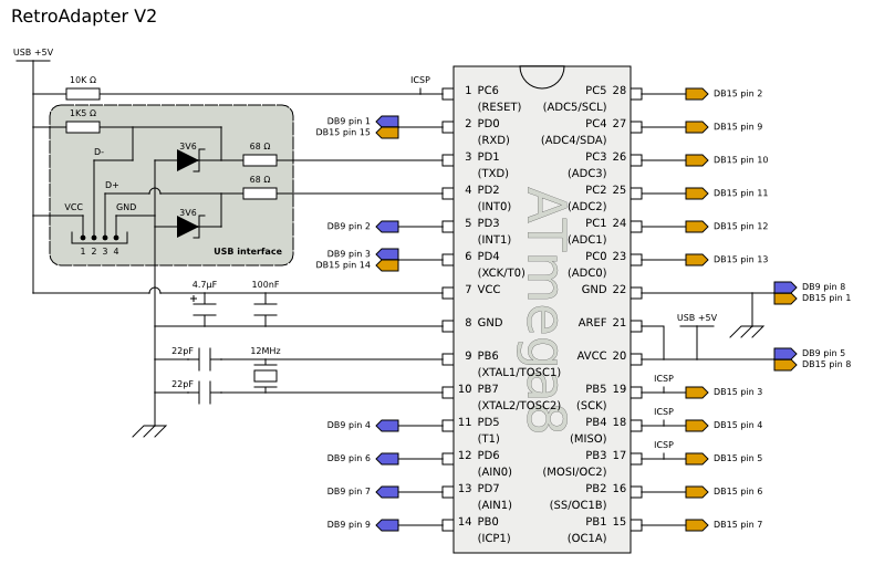
The circuit
This is the schematic diagram for RetroAdapter V2 (Wayback Machine) (based on the original schematic (Wayback Machine)):
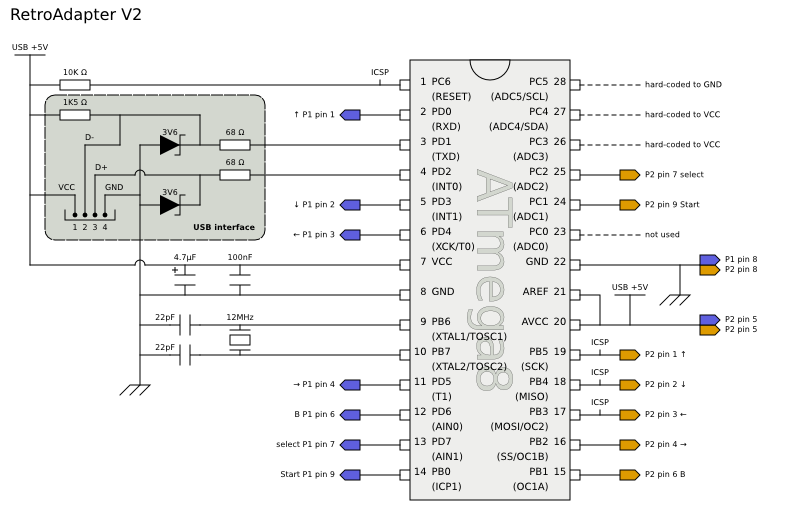
Since I’m only interested in SEGA Mega Drive gamepads, I can simplify the circuit
Note: The colors for Player 1 and Player 2 connections in the diagram were chosen to be the exact same colors as Sonic and Tails.
The hardware
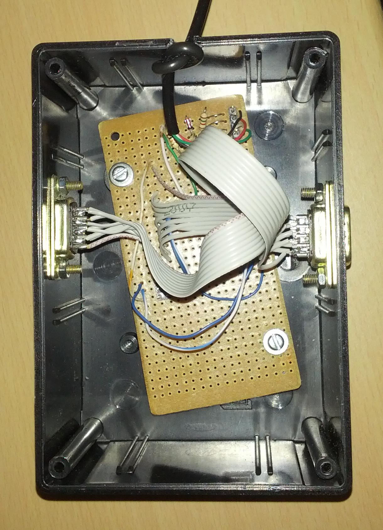
Here is a picture of the finished circuit board (sorry, I didn’t take any picture of the solder side):
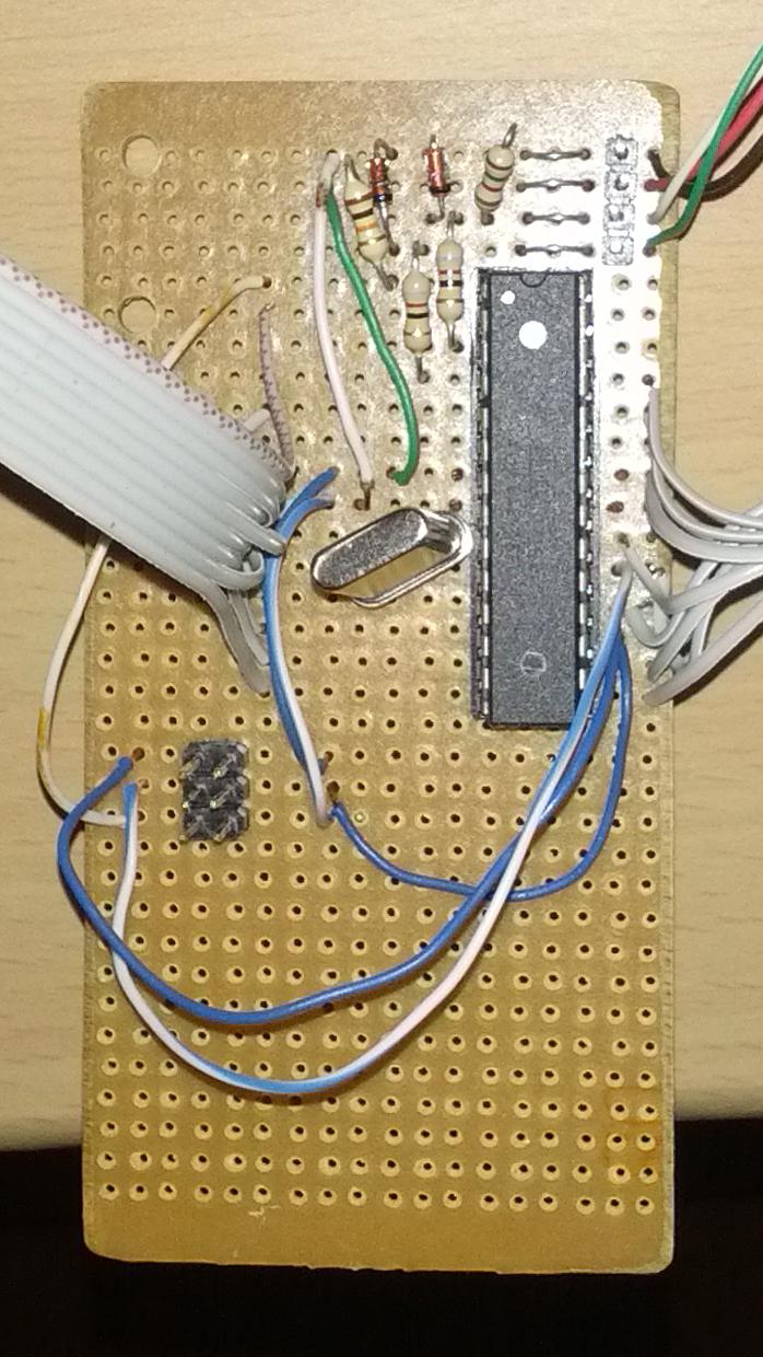
There are a few things I want to highlight at the previous picture:
- The 22pF capacitors are required by the ATmega8 datasheet, but my circuit worked well even without them.
- The 10µF (or 4.7µF) and 100nF capacitors are standard decoupling capacitors (Wayback Machine), and they are also missing from the finished circuit. I probably should have added them for increased stability.
- At the bottom-left, I’ve added a 6-pin header for in-circuit serial programming (ICSP).
- At the top-right, I’ve added a 4-pin header for the USB cable. If someday my current USB cable breaks, I can easily replace it without resoldering the board.
- The holes at top-left are arbitrary, I drilled them years ago. Still, I used one of those holes to attach the board to the plastic box with a screw. I had to drill another hole at bottom-right (not pictured) to attach a second screw.
While soldering all the pieces together, I used a multimeter to make sure everything was soldered correctly. Fortunately, I’ve managed to solder everything without any mistakes, and the board worked on the first try (woohoo!).
The firmware
After the board was ready, I went to my Gentoo Linux machine to prepare the firmware. It took a bit longer than expected, it was not really trivial, but it wasn’t too difficult either.
I had to adapt the Makefile, remove the code that used PCICR register (it is only available on newer AVR microncontrollers, it is not available on ATmega8), update the V-USB (Wayback Machine) driver to a newer version (to fix an error related to SIG_INTERRUPT0 being renamed to INT0_vect in newer compiler versions), and remove support for Amiga mouse and analogue BBC controllers (some compiler errors that I didn’t bother to fix, as I won’t ever use those controllers). After these changes, the firmware size was around 7KB. Yes, it fits into ATmega8’s 8KB ROM, but it won’t fit into the 6KB limit if I decide to also use a bootloader. So I continued disabling other modules that I won’t ever use (PC-Engine, PC-FX, 3DO, Atari driving, SNES mouse…). Great! The firmware is now under 6KB.
Then, I had to hard-code support for SEGA Mega Drive controllers on the DB15 port. In the original RetroAdapter design, the DB15-to-DB9 adapter would pull pins PC3 and PC4 to VCC, and pull pin PC5 to GND. This combination is read by the firmware through a sequence of if statements and is used to detect that the controller on the DB15 port is a second Mega Drive controller. Since I’m not using a DB15 port, and also I didn’t want to hard-wire those pins to specific logic values in the circuit (instead, I left those pins unconnected), I had to override this detection logic via software. Basically, I hard-coded those if statements to always run the Mega Drive controller branch.
After all these changes, it was time to write the firmware into the microntroller and test the device… And it works! On the first try! Amazing! Congratulations to Paul Qureshi for creating this project!
But it still had two small but annoying bugs: the Start and Mode buttons were mapped to the same button on the second Mega Drive controller, and the Start/Mode button mapping was different between the first and the second virtual USB joysticks. Both were trivial to fix.
Finally, the icing on the cake, I wanted to add the bootloader to my device, so would be able to update the firmware without requiring any extra device. It turned out to be harder than I thought, but in the end I’ve managed to use an updated version of USBaspLoader as the bootloader. Now, if I connect my RetroAdapter to a computer while holding the B button from any Mega Drive controller, it will boot into USBaspLoader mode, allowing firmware updates.
The final firmware with all my modifications is available as a git repository at GitHub.
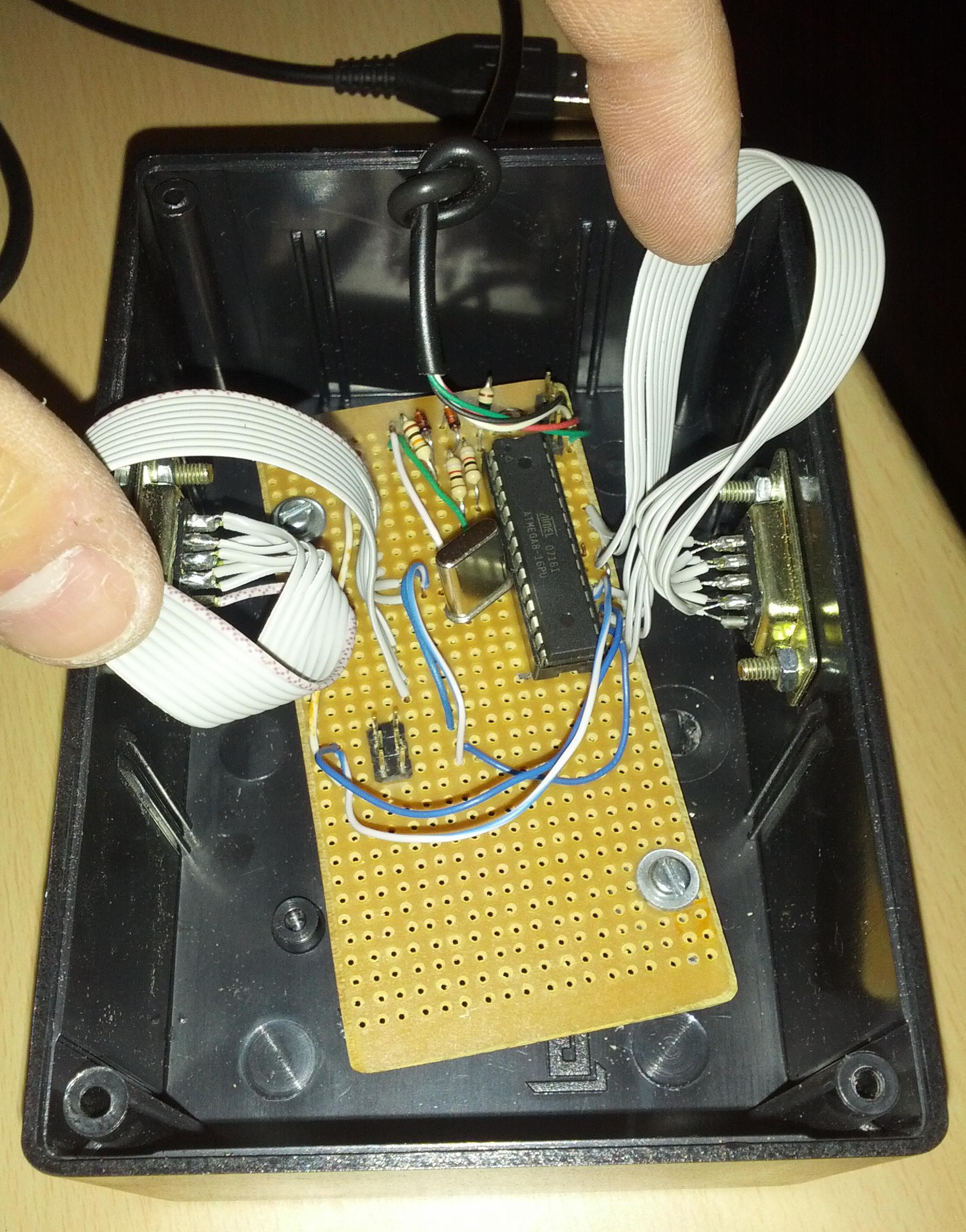
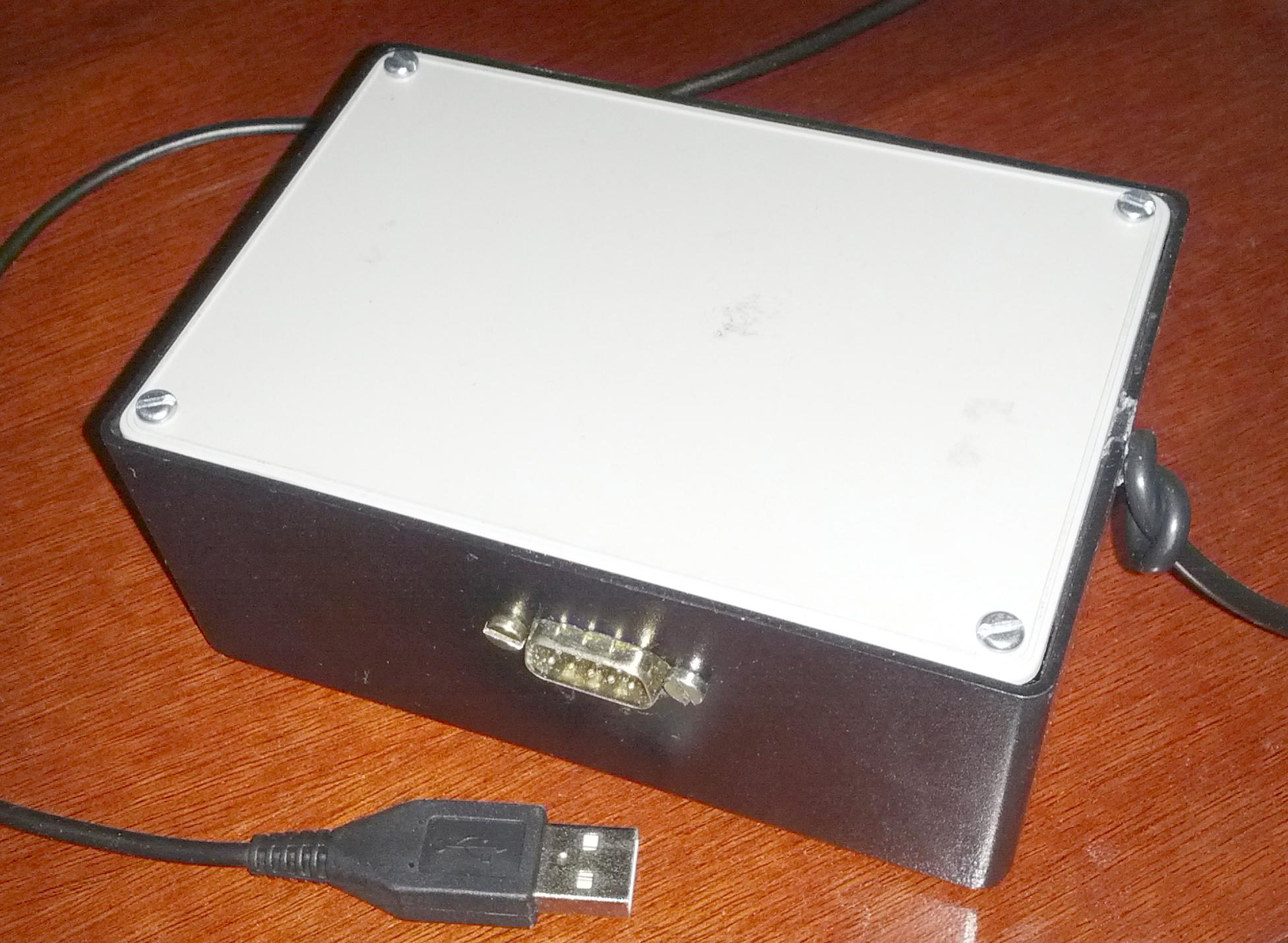
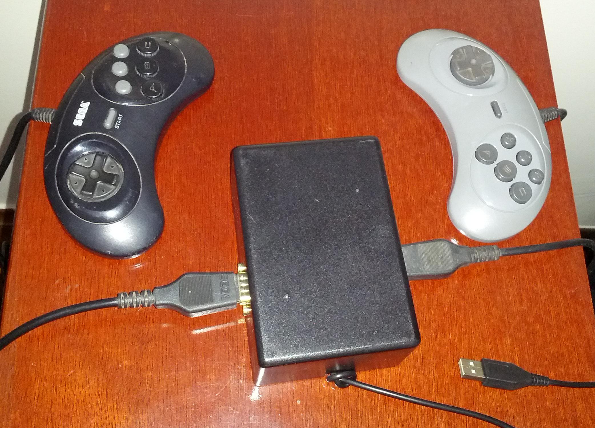
The finished product
After everything was working correctly, I bought a plastic box to hold the circuit. I also had to buy some screws, some nuts and some washers. I used a cheap soldering iron (that I won’t use for soldering electronic components) to melt holes in the plastic box, and I enlarged and smoothed those holes using some files.
This adapter works on both Linux, Windows and Android. Yes, I can connect it to a Android smartphone and use a SEGA Mega Drive joystick to control the Android device. How awesome is that? And it should also work on Mac, but I couldn’t test it because I don’t have one.
See also
- Retro Adapter homepage (Wayback Machine)
- Retro Adapter connections pinout
- My modified version of the firmware
- First contact with ATmega8 microcontroller, a multi-part series of posts where I explain how to work with AVR microcontrollers